If you've been following along on my journey to learn electronics design, you'll know I've been working on a motorcycle power supply. It's getting pretty close to finished and its time to do testing. The last series of blogs were about a constant current load testing device. I needed that to test the power supply under different load conditions. This installment is about the opposite end of that spectrum, what happens when the circuit is "off". Because lots of motorcycles tend to be parked for months without being ridden I need to verify that my device does not contribute to early battery failure. To do that I need to measure the current consumed when it is plugged in but off. We are talking about very small currents though so very high precision measurements are required.
Normally, you can use a digital multimeter for this purpose but for measuring small currents this not as straightforward as it seems. Ammeters are connected in series with a circuit and while a perfect ammeter would neither add or subtract anything to the circuit, it would just observe, in the real world ammeters are not perfect. Standard multimeters use a current shunt, or a resistor in series, and measure the voltage drop across that resistor. These designs unfortunately introduce something called burden voltage. This is the voltage dropped across the resistor used for measurement. This can be kept at a minimum by using small resistors but it cannot be avoided with a shunt ammeter. When you try to measure small currents with a DMM you can sometimes get grossly under reported currents caused by the burden voltage of the measurement circuit. 1
An alternate method is to use a feedback ammeter which measures the voltage dropped across the shunt and adds that much voltage back into the circuit. This sounds fancy but in fact is not that complicated once explained. That is my intention today.
 |
| Feedback Ammeter |
This schematic makes it look so easy and I despite my best efforts to build it true to this diagram I failed to find success. The secret sauce is how you power the op amp. In order for me to make it work, I needed a floating power supply and I needed it referenced such that half of the floating power supply's potential was above GND and half was below GND. The wikipedia page 2 offered the tidbit about the floating power supply. With that I was able to get a voltage measurement that was proportional to the current input but there was a DC offset that changed with the voltage applied to the op amps. Dave Jones' uCurrent device's schematic 3 offered the final missing piece which was the referencing the power supply to half the potential. Once I got that figure the circuit was a winner!
Useful resources:
www.keithley.com/data?asset=6169
http://www.ni.com/white-paper/5448/en
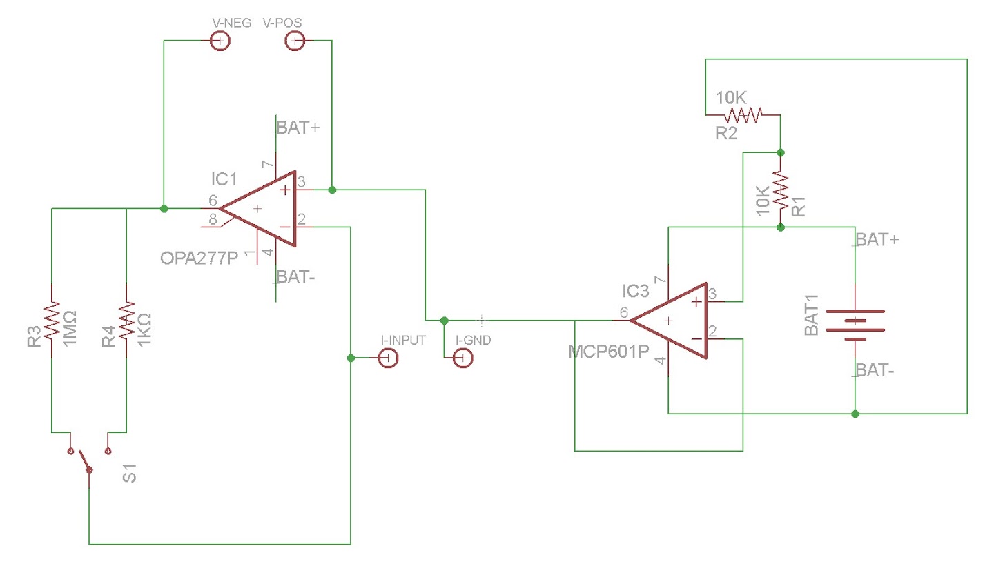 |
| My schematic |
 |
| Circuit on breadboad |
Really great video..this is a transimpedance amplifier rite..i didnt understand the final voltage measuring part..if i m not wrong this circuit measure very low current in uamp to nano amp range current and convert it to voltage right..m sry m not a very technical person.. i was really hoping if i could get a little help in my project regarding this. in my project the current will be in nano amp range coming from laser based gas detector and will be using a tuning fork. i have to convert this small current into voltage and amplify.. and the gain should be maximum and this should work in frequency range 15-50 khz. can i use the exact same circuit for this purpose or how do i adjust the frequency range? or what modifications could i do to use it in my project? your help would be really really appreciated. it is very urgent so i thought u would be a great help...thankyou :)
ReplyDeleteplease reply asap @ osh.yen26@gmail.com
Thankyou very much :)