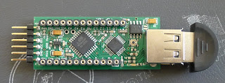
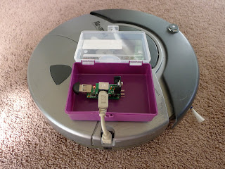
I've been working on an Arduino compatible Mini USB Host board. Well, I've had it done for a while now. I've slowly been compiling a bunch of projects for it so I can give it a cool Kickstarter one of these days. To that end, I designed a dedicated shield for controlling a Roomba vacuum with a Wii remote controller so that it might make the entirety of the project more compelling.
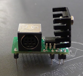
I'd already written the firmware and tested it with a chopped and spliced up cable a few months ago. It worked well for a while but one day the entire thing shot craps. My belief is that the on board voltage regulators could not handle the 16V the Roomba outputs (too much voltage to drop with an LDO without good cooling). So, for the dedicated board I decided to put a TO-220 7805 regulator with a heatsink on it. That should protect the main board from damage. I also had the idea of using optocouplers to isolate the Roomba signals from the shield. Optocouplers are ICs that contain an internal LED that turns on when a voltage is applied. That light shines on a photo detector which creates a voltage on the base of BJT opening a channel for current to run. This means two circuits can communicate without having any conductors between them. They isolate distinct circuits in effect. This seemed unnecessary but the board just had enough room and the datasheet gave the impression it would work (foreshadowing).
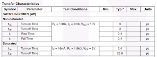
I bodged up the board and got the voltage dropoff speeds into the 25µs range and was hopeful. I plugged it in and ended up with a Roomba that was, well, drunk. It moved slow and listed to one side. No dice.
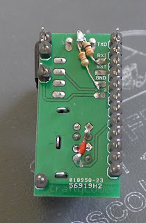
I grabbed another board from the bag and built up a fresh one wiring around the optocoupler.


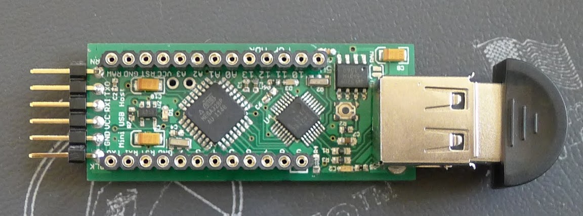
I'd already written the firmware and tested it with a chopped and spliced up cable a few months ago. It worked well for a while but one day the entire thing shot craps. My belief is that the on board voltage regulators could not handle the 16V the Roomba outputs (too much voltage to drop with an LDO without good cooling). So, for the dedicated board I decided to put a TO-220 7805 regulator with a heatsink on it. That should protect the main board from damage. I also had the idea of using optocouplers to isolate the Roomba signals from the shield. Optocouplers are ICs that contain an internal LED that turns on when a voltage is applied. That light shines on a photo detector which creates a voltage on the base of BJT opening a channel for current to run. This means two circuits can communicate without having any conductors between them. They isolate distinct circuits in effect. This seemed unnecessary but the board just had enough room and the datasheet gave the impression it would work (foreshadowing).
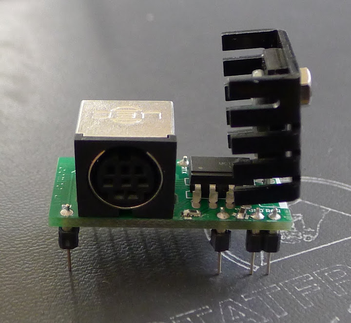
I built it up and put it together and I got nothing. The multimeter tests I conducted gave me no guidance either. I put voltage on one side of the optocoupler and I get a voltage out on the other side, or so I though. I put it on the oscilloscope and once again learned the value of good tools. The scope showed me that the clear problem was that the optocoupler is slow to respond. It can handle changes at human speeds but not a the speeds I was signalling. The initial speed was something like 300mS to drop off to 0V. That is glacial! The datasheet suggested 3µs was the expected value so I clear did something wrong. I read it closely and saw the RL needs to be 100Ω for that to work like that.

Time for a little rework.

I grabbed another board from the bag and built up a fresh one wiring around the optocoupler.
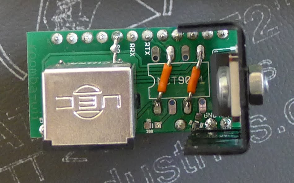

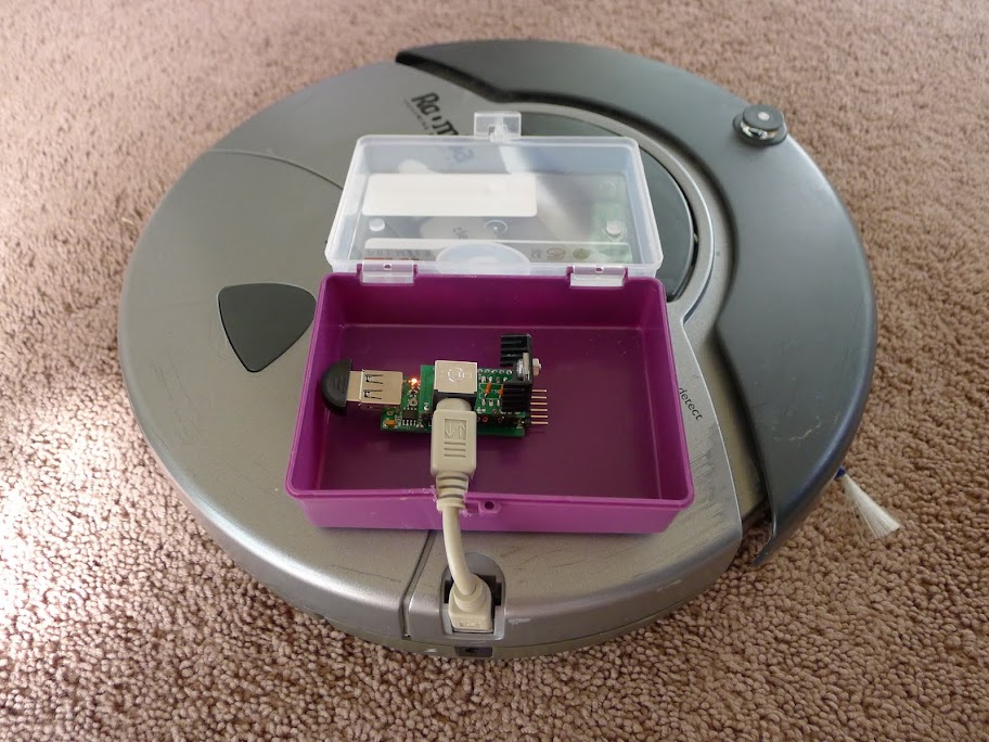
I bundled it up and gave it to my son Zev. Have fun son.
Comments
Post a Comment