A diverse group of coders, makers, artists, scientists, system security researchers creating a hacker/maker space in Atlanta Georgia. We create new and exciting projects using diverse knowledge and teach free classes on a multitude of topics for the general public.
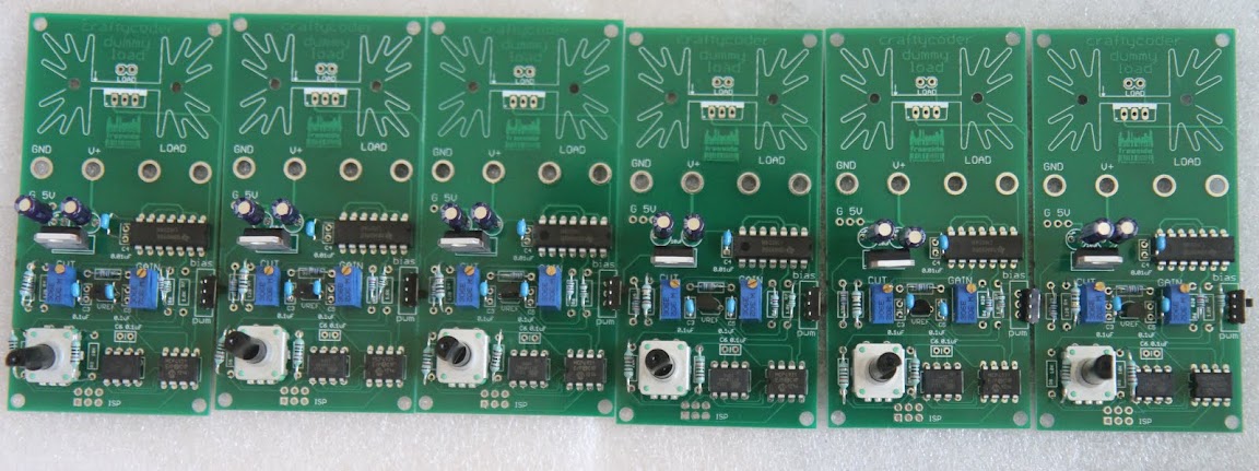
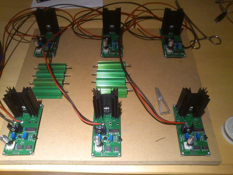
The project is finished. The units have been built and sent off for use. Much was learned. Here are some insights.
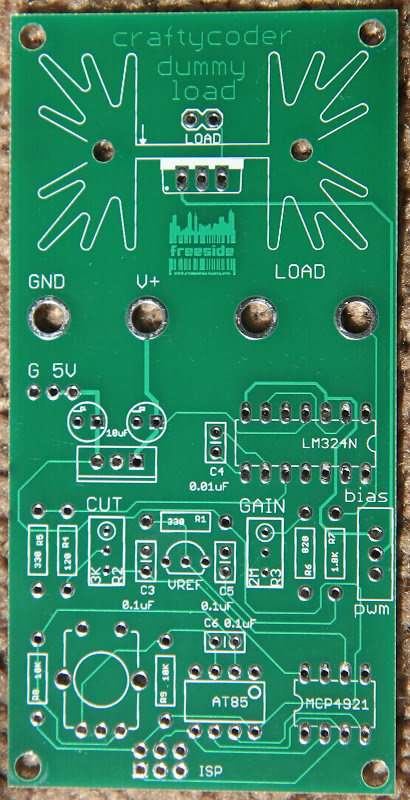
First, don't design a PCB for the lowest cost. That just increases your costs later. I made the the board narrower than was convenient to save $20 and I ended up wanting to put the entire thing a case so I could mount the banana adapters off the PCB where they could be farther apart. Not necessary but preferred for me.
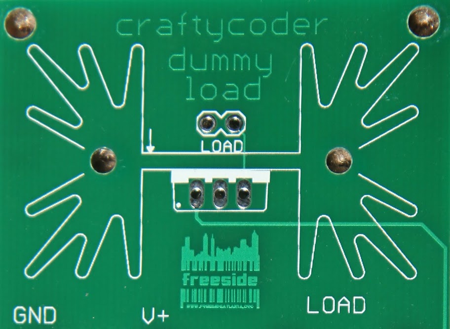
Second, putting artwork in copper on your PCB not only works but looks great when you are finished. Take a look at the second photo below. That Freeside logo looks awesome!
Third, assembly of through hole components is NOT easier than surface mount parts. It was a bit of a pain to build them all. TH components don't stay in place when you flip it over to solder.
Last weekend (February 10-12, 2017) I made a Janko-layout capacitive-touch keyboard for the Moog Werkstatt at the Georgia Tech Moog Hackathon. The day after (Monday the 13th), I made this short video of the keyboard being played: "Capacitive Touch Janko Keyboard for Moog Werkstatt" (Text from the video doobly doo) This is a Janko-layout touch keyboard I made at the 2017 Moog Hackathon at Georgia Tech, February 10-12. I'm playing a few classic bass and melody lines from popular and classic tunes. I only have one octave (13 notes) connected so far. The capacitive touch sensors use MPR121 capacitive-touch chips, on breakout boards from Adafruit (Moog Hackathon sponsor Sparkfun makes a similar board for the same chip). The example code from Adafruit was modified to read four boards (using the Adafruit library and making four sensor objects and initializing each to one of the four I2C addresses is remarkably easy for anyone with moderate familiarity with C++), and ...
It's been a while since we posted a progress report for the Atlanta Cosplay Meetup's ongoing project, and with Dragon Con right around the corner, we're nearing the finish line. Let's take a look and see what's been going on the last few months! Check out our previous progress reports here: Progress update #1 Progress update #2 Read on to see where we're at now...


did you have pcb ok kit?
ReplyDeletecan your dummy load design use for supply 80V 10A??
ReplyDeleteI try to make my dummy load using IRF540 with 0.1Ohm 40Watt ,, but IRF getting HOT and also LM324 N getting burn..
if the LM324 is getting hot the whole circuit is likely oscillating. It is very hard to get an opamp/mosfet running in linear mode to be stable.
ReplyDelete