A diverse group of coders, makers, artists, scientists, system security researchers creating a hacker/maker space in Atlanta Georgia. We create new and exciting projects using diverse knowledge and teach free classes on a multitude of topics for the general public.
Since the last installment, I've finalized the initial PCB design and sent it off to Seeedstudio for fabrication. I've never designed a through-hole (TH) construction board before but in general all the same rules apply to SMD and TH boards I believe.
200W 0.1Ω load
30W 1Ω load
10x10Ω 3W in ||
25 turn
trimmer pot
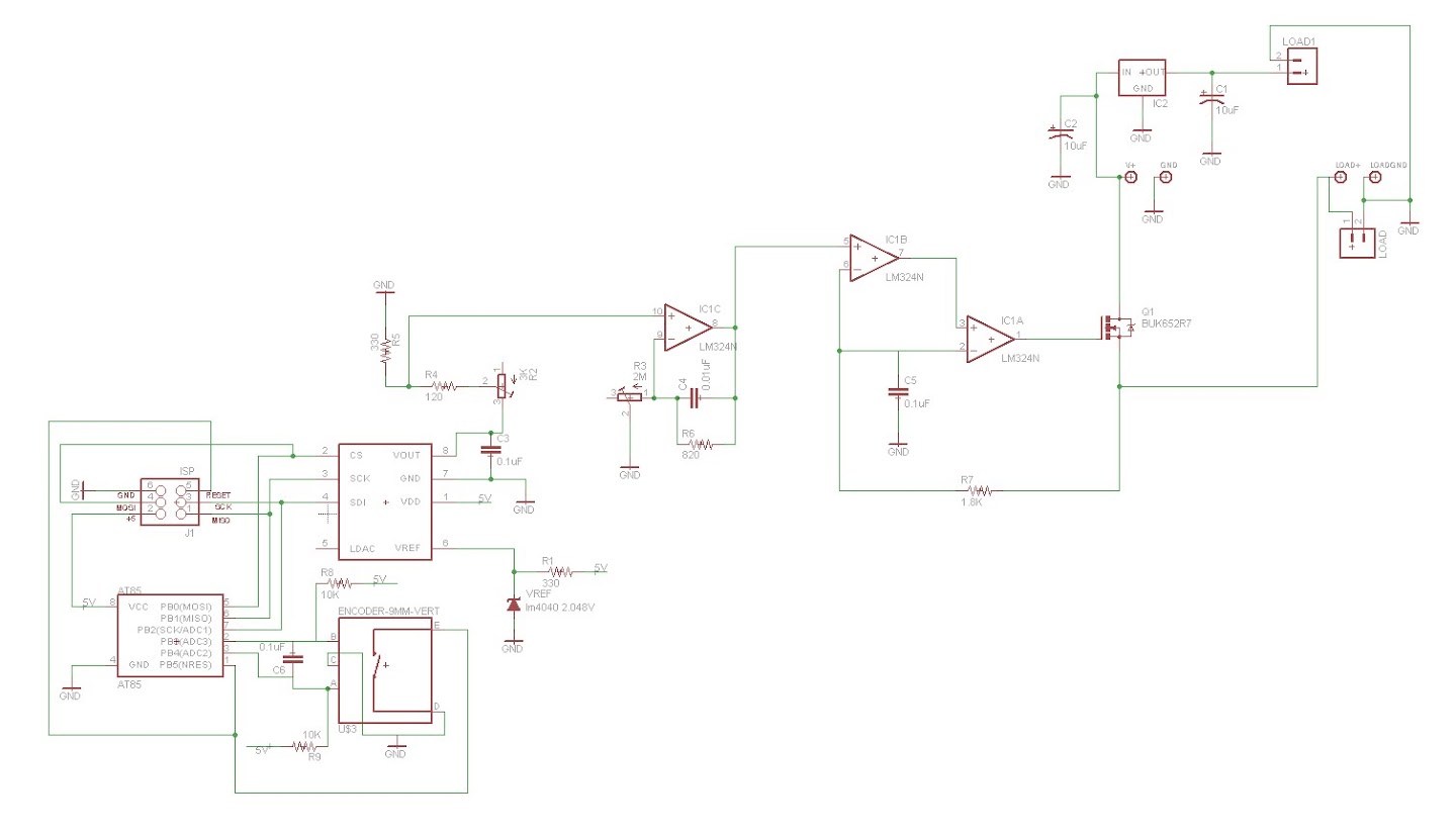
I changed up a few things during the PCB design phase of this project that I thought would be interesting to mention. I added a pair of trim pots to design. One trim pot reduces the maximum voltage going into the first op-amp stage. The second is the in the feedback loop of the first op amp stage. At maximum resistance, 3000Ω to GND (R2 of the voltage divider), with the 820Ω R1 (there for its role as a low pass filter in addition to the voltage divider), I should see a 27% voltage gain. Turned down to 0Ω, that pot creates a situation where the output is the high output voltage of the op-amp (essentially infinite gain). Something like 8V for the op-amp/input voltage I am using. Why did I bother to design a mechanism to adjust the highest voltage output across the load down to200mV and up to 8V? Well, so I could use a bunch of different load resistors with this circuit and not have to worry about lighting anything on fire with the knob after setting trimmers to their "final" value. I 0.1Ω load resistor is going to burn 10 times the current of a given voltage than a 1Ω resistor so it occurred to me that having a flexible system made a lot of sense. I got the trimmers on ebay for a quarter each, so while they are much more expensive than a normal resistor, they save me having to build a different board for each load resistor. You can trim it up for a given load within a minute with just a multimeter.
Basic MOSFET operating voltage graph
I also included to a switch so the user can switch between operating the main current MOSFET in the linear region (aka triode mode or ohmic region) or in the saturation region (aka active mode or fully enhanced). You can operate the MOSFET in the ohmic region by applying a relatively flat DC voltage on the MOSFET gate below the saturation voltage. The MOSFET behaves like a adjustable resistor in this mode. When operated in the saturation region (by putting high voltage on the gate) the MOSFET channel has its lowest possible resistance it has to offer but as a result you need to switch it on and off in order to limit the current. I hypothesize that the MOSFET will run cooler at a constant current in saturation mode then it will in the ohmic region but it remains to be tested. I decided to offer both options in the circuit because I figure both have their objective value. I show the difference on the scope in the video above.
In addition to these admittedly minor hardware revisions I also created the previously posted rotary encoder library so I could have both fine and course control over the output current. Might as well take full advantage of the digital circuitry, right?
The two holes labeled "LOAD" top center of the PCB rendering below are points you can use to measure the voltage across the load. That number, with a little basic Ohm's Law calculus, will tell you the current going through your load. It will be a useful point to pull data for an analog panel meter. The boards should be here within a couple weeks and then I'll build a couple up and post them up. I'll also bring one to Freeside to put on the shelf. It's always handy to have a precision load when doing electronics work.
I added the Freeside logo in copper on the top of the board.
It will be interesting to see how that looks in real life.
Last weekend (February 10-12, 2017) I made a Janko-layout capacitive-touch keyboard for the Moog Werkstatt at the Georgia Tech Moog Hackathon. The day after (Monday the 13th), I made this short video of the keyboard being played: "Capacitive Touch Janko Keyboard for Moog Werkstatt" (Text from the video doobly doo) This is a Janko-layout touch keyboard I made at the 2017 Moog Hackathon at Georgia Tech, February 10-12. I'm playing a few classic bass and melody lines from popular and classic tunes. I only have one octave (13 notes) connected so far. The capacitive touch sensors use MPR121 capacitive-touch chips, on breakout boards from Adafruit (Moog Hackathon sponsor Sparkfun makes a similar board for the same chip). The example code from Adafruit was modified to read four boards (using the Adafruit library and making four sensor objects and initializing each to one of the four I2C addresses is remarkably easy for anyone with moderate familiarity with C++), and ...
It's been a while since we posted a progress report for the Atlanta Cosplay Meetup's ongoing project, and with Dragon Con right around the corner, we're nearing the finish line. Let's take a look and see what's been going on the last few months! Check out our previous progress reports here: Progress update #1 Progress update #2 Read on to see where we're at now...


how much is pcb?
ReplyDeleteAbout $3 each in quantities of 10.
ReplyDelete