Update: Arduino Library Released
If any of you guys were at Freeside this weekend, you would have seen me staring into the oscilloscope trying to make heads or tails of its output and comparing that to a couple of datasheets. One of those datasheets was for the Atmega328P microcontroller that is on the Arduino UNO, the other was the Sharp Memory LCD. These are cool because the are ultra low power 6uW and have extremely high contrast.
The Sharp datasheet isn't what I would call straightforward, at least for the uninitiated (whom I count myself among). The power up sequence was pretty clear but once it came to pushing pixels it got a little vague. Really it was just a bunch of waves on the sheet.
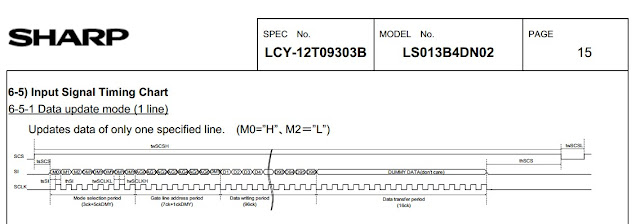

One of the waves is a constant 5-60Hz pulse. That is the sort of thing that would be very irritating to create if you are bit banging on the main loop of your program, so I needed to get the AVR to pump that out in an automatic way. Researching the interwebz and reading the Atmega datasheet at length and comparing that to the output on the o-scope, I came up with this:
This is the code that produces the images in the video above. The library is not link up yet. I'll make a google code project for this once I have it a little more mature. Feel free to post up a comment if you want a pre-release copy. I'll hook you up.
If any of you guys were at Freeside this weekend, you would have seen me staring into the oscilloscope trying to make heads or tails of its output and comparing that to a couple of datasheets. One of those datasheets was for the Atmega328P microcontroller that is on the Arduino UNO, the other was the Sharp Memory LCD. These are cool because the are ultra low power 6uW and have extremely high contrast.
The Sharp datasheet isn't what I would call straightforward, at least for the uninitiated (whom I count myself among). The power up sequence was pretty clear but once it came to pushing pixels it got a little vague. Really it was just a bunch of waves on the sheet.
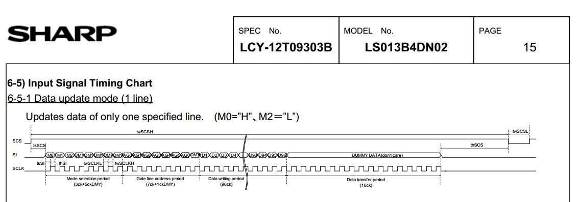

One of the waves is a constant 5-60Hz pulse. That is the sort of thing that would be very irritating to create if you are bit banging on the main loop of your program, so I needed to get the AVR to pump that out in an automatic way. Researching the interwebz and reading the Atmega datasheet at length and comparing that to the output on the o-scope, I came up with this:
pinMode(11, OUTPUT);
TCCR2A = _BV(COM2A0) | _BV(COM2B1) | _BV(WGM20);
TCCR2B = _BV(WGM22) | _BV(CS22) | _BV(CS21) | _BV(CS20);
OCR2A = 65; // 60HZ roughly
int bang = 0;
void loop() {
  pinMode(9, OUTPUT);
  if(bang == 0) {
    digitalWrite(9,HIGH);
    bang = 1;
  } else {
    digitalWrite(9,LOW);
    bang = 0;
  }
  delayMicroseconds(8333);
}
The prior code puts out a "phase correct" square wave on pin 11 at 60Hz. It also screws with pin 3 (not good) which I need to address next time I am at a scope. With that, it was just a matter of reading the data sheet for the screen and deciphering the thing into C code. I also found a non-arduino project on youtube using one of these screens and asked the poster to send me his source which was very helpful in understanding the datasheet. Once that was done, I converted that C code into C++ code and made a "SharpMemoryLCD" Arduino library. Currently it can print out basic strings and read byte[]s from PROGMEM and paste them to the screen. I will also add some other features like painting vectors to the screen and loading bitmaps from a disk before I'll call it "done". The current functionality is enough to get the reflow oven project I am working on finished though. That reflow oven project will be the basis of a future Freeside project/class where attendees will get a custom PCB and firmware to use to convert their toaster oven into a high quality reflow oven. You will be required to bring a 1500W toaster oven, and I think the rest of the stuff I'll include in the class fee (custom electronics, solid state relays, and thermocouples).
This is the code that produces the images in the video above. The library is not link up yet. I'll make a google code project for this once I have it a little more mature. Feel free to post up a comment if you want a pre-release copy. I'll hook you up.
#include "SharpMemoryLcd.h"

SHARPMEMORYLCD lcd;

void setup() {
  Serial.begin(57600);
  lcd.LcdInitialize();
  lcd.LcdAllClearMode();
  lcd.LcdStartEXTC();

}

void loop() {
  lcd.LcdPrintString("  CRAFTYCODER'S",4);
  delay(1000);
  lcd.LcdPrintString("  WIFE COMES HOME",7);
  delay(1000);
  lcd.LcdStopEXTC();
  lcd.LcdAllClearMode();
  lcd.LcdStartEXTC();
  lcd.LcdPrintImage();
  delay(1000);
  lcd.LcdStopEXTC();
  lcd.LcdAllClearMode();
  lcd.LcdStartEXTC();
}
Comments
Post a Comment