
ISP Programming Jig w/ pogo pegs


During one of the last projects I was working on, I found that the first programming jig I made had a serious draw back. It could only put the #1 pin of the programmer in two of the four corners. That meant that I could only program my board from one side. That was fine until I assembled the project in it's case. At that point, reprogramming was a difficult task that required disassembly, something I never considered when I designed the item and as it turned out it was almost impossible to do without destroying it. Annoying!

Three weeks ago I decided I wanted to flash some new firmware on my motorcycle remote so I could use it to put a GPS on my Kindle Fire. That meant I needed take it apart and risk destroying it. Not an exciting prospect. Then I thought, why don't I just build another programming jig like the last one only upside down. That seemed like a winner, because it was fast, but I didn't have any more 2x3 ISP headers. Bah! Since I needed to wait on a shipment from Digikey I went ahead drew up a custom circuit board and added a few bells and whistles and sent it to fabricator. 

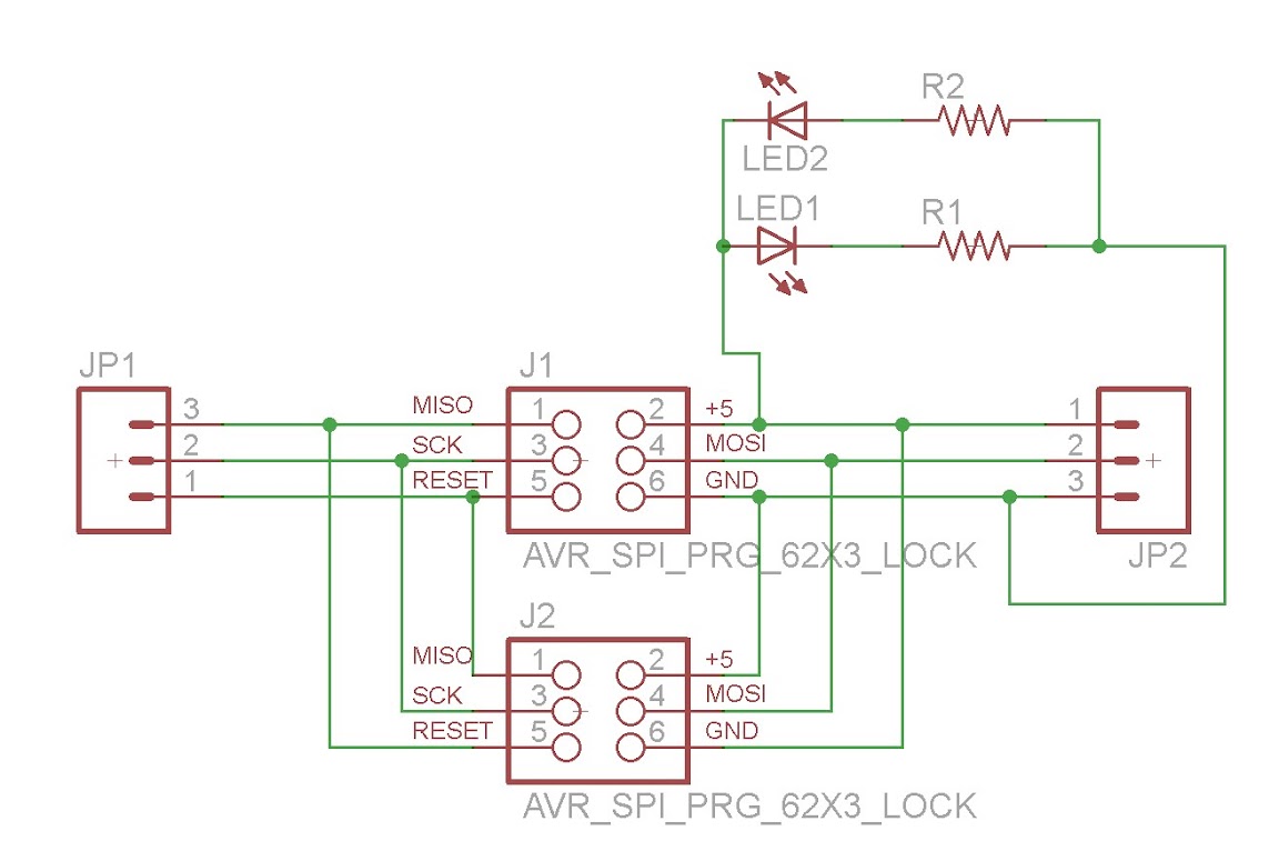
The bells and whistles I spoke of are a pair of ISP headers which are mirror images of each other and a pair of LEDs that point to the #1 pin. When you plug into one the of the two headers, one of the two LEDs lights up pointing to the #1 pin. This function makes it easy to identify how to orient the PCB to the jig.

Below are images of the schematic and the board layout. The assembly is very easy. You just take two of the PCBs solder a pair of headers to the bottom board and pogo pegs to both and use some stand offs for strength. Check out the video for a better look at the final assembly.

You can modify the Eagle files posted below or send the pre-configured Gerber files directly to http://oshpark.com/ or your preferred fabricator to get some PCBs of your own.
Link to Eagle and Gerber Files


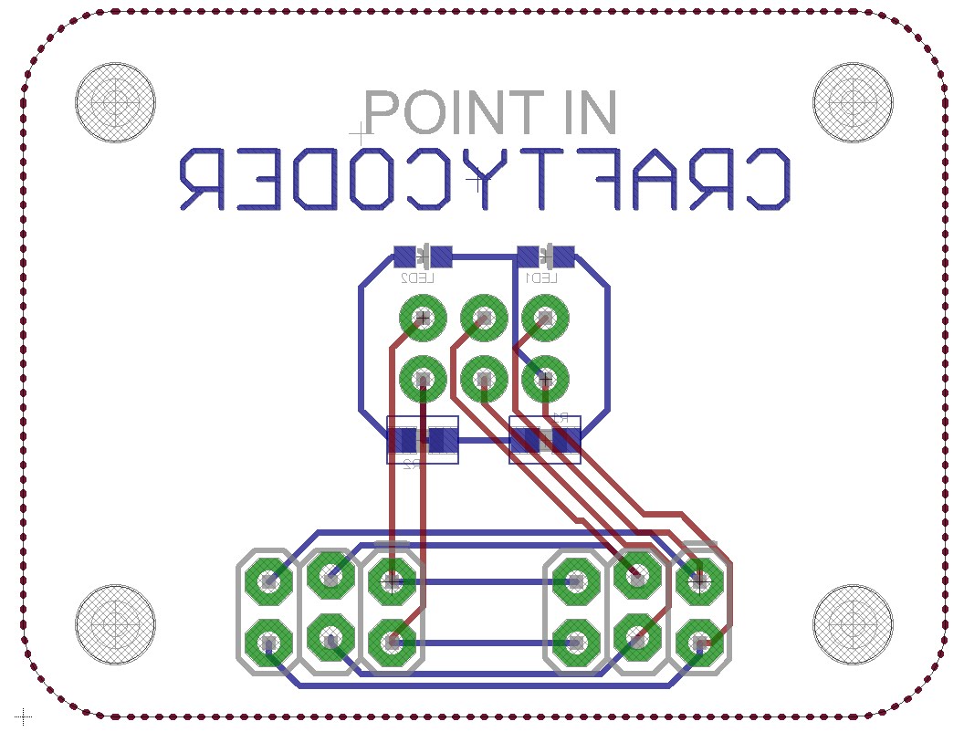
I drew up the board upside down for no particular reason.
Blue is the outside and red is the inside.

Comments

Popular posts from this blog

A Capacitive-Touch Janko Keyboard: What I Did at the 2017 Georgia Tech Moog Hackathon

Last weekend (February 10-12, 2017) I made a Janko-layout capacitive-touch keyboard for the Moog Werkstatt at the Georgia Tech Moog Hackathon. The day after (Monday the 13th), I made this short video of the keyboard being played: "Capacitive Touch Janko Keyboard for Moog Werkstatt" (Text from the video doobly doo) This is a Janko-layout touch keyboard I made at the 2017 Moog Hackathon at Georgia Tech, February 10-12. I'm playing a few classic bass and melody lines from popular and classic tunes. I only have one octave (13 notes) connected so far. The capacitive touch sensors use MPR121 capacitive-touch chips, on breakout boards from Adafruit (Moog Hackathon sponsor Sparkfun makes a similar board for the same chip). The example code from Adafruit was modified to read four boards (using the Adafruit library and making four sensor objects and initializing each to one of the four I2C addresses is remarkably easy for anyone with moderate familiarity with C++), and

Freesiders Hackers Collaborate in Medical / Surgical Research

Published in the May issue of the Journal of Foot and Ankle Surgery : " A Novel Combination of Printed 3-Dimensional Anatomic Templates and Computer-assisted Surgical Simulation for Virtual Preoperative Planning in Charcot Foot Reconstruction ." This collaboration of specialties represents an undertaking by members of Freeside Atlanta , Southern Arizona Limb Salvage Alliance , and The Podiatry Institute .  Charcot foot reconstruction remains on of the most challenging procedures in foot and ankle surgery.  These procedures are often lengthy procedures which can be riddled with complications. With the help of Freeside Atlanta Members, institutional researchers used open source Osirix Image viewer and 3D Software such as Newtek's Lightwave or Blender to create simulated surgical reductions as well as 3D printed templates.  Freeside Atlanta members assisted in providing 3D printing solutions and know-how to the project. Experimental test prints were done on a M

Onboard Firmware of the Human Brain

Freesiders are continually tinkering with robotics and other such machinery .  Many of these embedded processors and firmware are becoming open source and every-more diversified in the wake of the modern Maker movement . One notable boost to the hackerspace arsenal is the Arduino (an like platforms).  This offers designers an incredible power to devise not just individual devices but even the emergence of complex, integrated systems . This evolutionary pace of modern technological systems may be significantly faster the biologic system development, but there may be a few well learned tricks yet to be mastered.  It seems that studying how nature has managed to solve many development challenges will aid in designing robotics, where efficiently counts just as much. One  challenge, that is particularly interesting, is data processing.  Artificial intelligence is labored with processing data and producing a meaningful and useful output.  When considering the increase in sensory