I found myself needing a 480W power supply to test a high current project I was working on. A 500W bench/lab power supply will set you back $100s so I figured a PC power supply was the cheapest bet. For $80 you can get a Wonhunglow brand. I checked ebay and found Dell 500W server power supplies CHEAP. Like $2 cheap.
I acquired a couple and figured out how to turn the thing on by shorting 3 pins together. Then I designed a simple little 4 rail power supply PCB and had it built by OSH Park. This power supply outputs 12V and 5V and 4V. I didn't have any use for the 4V so I skipped those pins but did add a 500mA 3.3V LDO to my board so I have 3.3V, 5V, 12V, and GND rails available. I left a large section of the solder mask missing so I could solder on some more current carrying capacity and called it done. I used a DPDT switch to short out the 3 pins required to turn on the 12V rail and added a little LED to indicate that the 3.3V regulator was running and put a small current limiting resistor on the LED so that the regulator is stabilized (I didn't check the datasheet too closely but it is common for an LDO to behave strangely until it has a minimum load). One minor complicating factor was the unusual connector on this hot swappable power supply. It had a part number on it though and I was able to get Molex to send me a couple mating adapters.
I will redesign this with a fully adjustable constant voltage and constant current output in the the future. That will be a bit of a project because 500W is a lot of power to bleed off and I want it to be accurate so I plan to use 12bit DACs and ADCs. I've been looking around for them and they are expensive enough that I think I will just use a ARM Cortex 3 microcontroller with on board 12 bit converters. More on that on some future post.
Here it is.
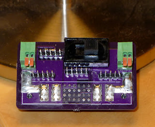 |
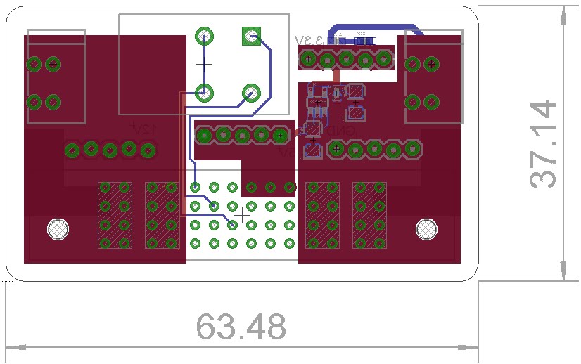
| The business end. |
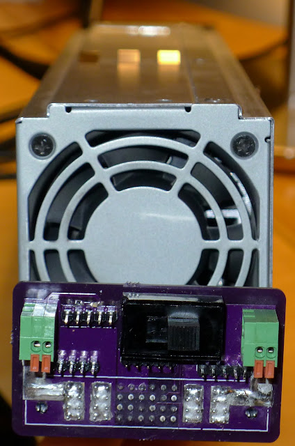
 |
| Plugged into the Power Supply |
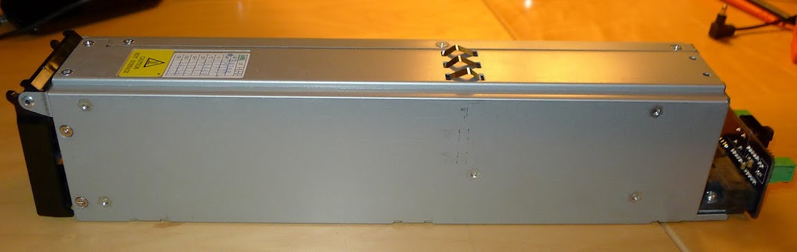
 |
| Side view of the Power Supply with PCB attached |
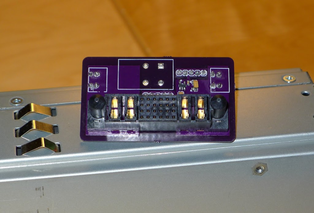
 |
| The back side featuring the LDO and Molex connector. |


Comments
Post a Comment