Hello, Freeside readers, and welcome to my first blog post!
My name is Michelle Sleeper, I am a prop and costume builder in Atlanta, working primarily out of Freeside's space. I have been building costumes and plastic space guns since 2001, and have been a member of Freeside since 2013.
My most recent major project was to upgrade a costume I built last year of the Marvel comic's character, Ultron. The costume owner wanted a new and improved helmet, made of cast resin and full of all sorts of lights. It was a big and ambitious project, and I was very excited to get started.

Here's how we got there.
From the outset we decided that we wanted the master sculpt to be 3D printed - but for those of you familiar with 3D printing, you know that extremely large prints are difficult if not impossible to produce. Most often, you will have to break your model up into many different segments, which you then assemble like a 3D jigsaw puzzle. We opted not to do that, and instead outsourced to a professional 3D printing company based in Florida called TheObjectShop. They have a Zcorp 650, which is a very large printer that prints in a plaster like material, which is then hardened with cyanoacrylate AKA super glue.
The resulting print, while expensive, was absolutely phenomenal.


Like all 3D prints, the surface had a texture to it that was unsuitable for our needs. I set about cleaning up the surface to as smooth as I could get it, a process which took about 2 and a half weeks. The process is simple - spray the piece with filler primer, fill any large problem areas with bondo or spot filler, and use increasingly finer grits of sandpaper - but extremely tedious and time consuming. I started at 80 grit to knock down some of the bigger problem areas, and worked my way up to 800 grit wet sanding. The results were a helmet that was nearly flawless.


Now that our master sculpt was completed, we had to create a 2 part jacket mold out of silicone. This would allow us to produce many different copies in urethane resin later down the line. Urethane resin is lighter weight and more sturdy than the brittle plaster 3D print. These are important factors, considering it would be worn for 6-8 hours a day (if not more) and require a bunch of electronics glued and bolted inside of it.
To create the 2 part mold, first we have to make a parting wall all the way around the helmet, which will be the interfacing layer where the 2 sides of the silicone molds touch. We use the end of our Xacto knife to create little bumps all along the edge, which are registration keys that help the two halves line up properly.


Once the first half of the silicone mold is applied, we flip the whole thing over, remove the parting wall, and apply a coat of releasing agent before we apply the second half of silicone. The releasing agent is absolutely critical - silicone will not stick to anything except other silicone. Without the releasing agent, we would essentially create a big silicone bowl which would be next to impossible to use for our purposes.


Once both halves of the silicone mold were created and fully cured, we created an outer rigid mother mold. This is used to keep the silicone mold held together, once the master is removed and the mold is hollow. It is also applied in two halves, and like the silicone we use a releasing agent when creating the second half.


To make the hollow casting, we use a technique called rotocasting or slush casting. This is where you pour a bit of your urethane resin into the hollow mold and rotate it around so that it evenly coats all of the surfaces with a thin layer. This is done 4-5 times using several small batches of urethane resin, so that we ensure every surface has an even thickness. Because the mold weighs around 10 to 15 pounds before we put a drop of resin into it, and because each layer requires about 5 minutes of tossing it around, I decided to build handles to form into the mother mold. This makes the mother much easier to hold onto during the already strenuous rotocasting process.
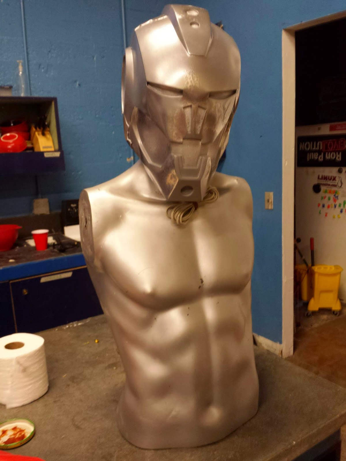
After you are finished casting, it's time to remove the mother and the silicone mold. What you are left with is a perfect reproduction of your master sculpt in a much lighter material. The casting process itself is a bit of a learning curve as every mold will be different. Certain areas will come out to be thinner than others, and the exact amount of material you need to use for each batch will depend on a lot of factors. What this means is that the first few castings will tend to be "duds", meaning they are unsuitable for your ultimate purposes - in our case, a wearable costume.


However, you can still dress up one of these bad casts and stick it on a mannequin to live in the space!
While we were working on sculpting the master and producing the molds, we were also working on the electronic guts that would go into the helmet. Specifically, there would be a set of LEDs set into laser cut acrylic, and a custom made 8 x 24 LED matrix for the mouth.
The eye LEDs are rather simple - I drew up a 2D design to bridge the width of the helmet's eyes, and then cut that out of 2 layers of opaque white acrylic. The inner layer was made of 6mm acrylic which the LEDs were set into and glued into place, and the outer 3mm layer was flat. The results are menacing glowing red eyes.

The mouth LED matrix, on the other hand, is worthy of it's own individual blog post, which I will be putting up later. The short version is that we found and used an Arduino Micro connected to three MAX7219 chips, which are designed to control an 8 x 8 matrix. The matrix had to be designed and wired up by hand, a process which took about 3 weeks of work. After some trial and error with the MAX7219 board kits we used, the whole thing was put together and worked flawlessly. Here is a test video of the center matrix in our temporary holder.
After the matrix was finished, a cover was laser cut out of 1mm clear acrylic and installed into the mouth. The LEDs were transferred into a similar housing for their permanent installation, and all of the boards were put into craft foam holders for protection and installed into the helmet. The results were nothing short of perfect!
At this point the project was finished and ready to be worn, but like any good project it has sparked a whole host of new ideas and "how to do it better"s.
Until next time!
Want to see more photos? Check out the complete build process on my Facebook page.
My name is Michelle Sleeper, I am a prop and costume builder in Atlanta, working primarily out of Freeside's space. I have been building costumes and plastic space guns since 2001, and have been a member of Freeside since 2013.
My most recent major project was to upgrade a costume I built last year of the Marvel comic's character, Ultron. The costume owner wanted a new and improved helmet, made of cast resin and full of all sorts of lights. It was a big and ambitious project, and I was very excited to get started.
Here's how we got there.
From the outset we decided that we wanted the master sculpt to be 3D printed - but for those of you familiar with 3D printing, you know that extremely large prints are difficult if not impossible to produce. Most often, you will have to break your model up into many different segments, which you then assemble like a 3D jigsaw puzzle. We opted not to do that, and instead outsourced to a professional 3D printing company based in Florida called TheObjectShop. They have a Zcorp 650, which is a very large printer that prints in a plaster like material, which is then hardened with cyanoacrylate AKA super glue.
The resulting print, while expensive, was absolutely phenomenal.
Like all 3D prints, the surface had a texture to it that was unsuitable for our needs. I set about cleaning up the surface to as smooth as I could get it, a process which took about 2 and a half weeks. The process is simple - spray the piece with filler primer, fill any large problem areas with bondo or spot filler, and use increasingly finer grits of sandpaper - but extremely tedious and time consuming. I started at 80 grit to knock down some of the bigger problem areas, and worked my way up to 800 grit wet sanding. The results were a helmet that was nearly flawless.
To create the 2 part mold, first we have to make a parting wall all the way around the helmet, which will be the interfacing layer where the 2 sides of the silicone molds touch. We use the end of our Xacto knife to create little bumps all along the edge, which are registration keys that help the two halves line up properly.
Once the first half of the silicone mold is applied, we flip the whole thing over, remove the parting wall, and apply a coat of releasing agent before we apply the second half of silicone. The releasing agent is absolutely critical - silicone will not stick to anything except other silicone. Without the releasing agent, we would essentially create a big silicone bowl which would be next to impossible to use for our purposes.
Once both halves of the silicone mold were created and fully cured, we created an outer rigid mother mold. This is used to keep the silicone mold held together, once the master is removed and the mold is hollow. It is also applied in two halves, and like the silicone we use a releasing agent when creating the second half.
To make the hollow casting, we use a technique called rotocasting or slush casting. This is where you pour a bit of your urethane resin into the hollow mold and rotate it around so that it evenly coats all of the surfaces with a thin layer. This is done 4-5 times using several small batches of urethane resin, so that we ensure every surface has an even thickness. Because the mold weighs around 10 to 15 pounds before we put a drop of resin into it, and because each layer requires about 5 minutes of tossing it around, I decided to build handles to form into the mother mold. This makes the mother much easier to hold onto during the already strenuous rotocasting process.
After you are finished casting, it's time to remove the mother and the silicone mold. What you are left with is a perfect reproduction of your master sculpt in a much lighter material. The casting process itself is a bit of a learning curve as every mold will be different. Certain areas will come out to be thinner than others, and the exact amount of material you need to use for each batch will depend on a lot of factors. What this means is that the first few castings will tend to be "duds", meaning they are unsuitable for your ultimate purposes - in our case, a wearable costume.
However, you can still dress up one of these bad casts and stick it on a mannequin to live in the space!
While we were working on sculpting the master and producing the molds, we were also working on the electronic guts that would go into the helmet. Specifically, there would be a set of LEDs set into laser cut acrylic, and a custom made 8 x 24 LED matrix for the mouth.
The eye LEDs are rather simple - I drew up a 2D design to bridge the width of the helmet's eyes, and then cut that out of 2 layers of opaque white acrylic. The inner layer was made of 6mm acrylic which the LEDs were set into and glued into place, and the outer 3mm layer was flat. The results are menacing glowing red eyes.
The mouth LED matrix, on the other hand, is worthy of it's own individual blog post, which I will be putting up later. The short version is that we found and used an Arduino Micro connected to three MAX7219 chips, which are designed to control an 8 x 8 matrix. The matrix had to be designed and wired up by hand, a process which took about 3 weeks of work. After some trial and error with the MAX7219 board kits we used, the whole thing was put together and worked flawlessly. Here is a test video of the center matrix in our temporary holder.
After the matrix was finished, a cover was laser cut out of 1mm clear acrylic and installed into the mouth. The LEDs were transferred into a similar housing for their permanent installation, and all of the boards were put into craft foam holders for protection and installed into the helmet. The results were nothing short of perfect!
At this point the project was finished and ready to be worn, but like any good project it has sparked a whole host of new ideas and "how to do it better"s.
Until next time!
Want to see more photos? Check out the complete build process on my Facebook page.
Comments
Post a Comment