Motobrain began when I decided my options for a vehicle fuse panel where too limited. I wanted something better. A buddy and I started chatting about what we might want from a fuse block and I started drawing schematics and making prototypes. My first idea was an actual fuse panel that could measure system voltage and total current draw and had fused circuits. It's "killer" feature was that all the outputs were interchangeable so you could select the type of output you wanted. It had card slots and the card slots and the cards I developed with for high side switching, low side switching, USB charging, and analog inputs. It was cool, but not really durable enough for an automotive environment.
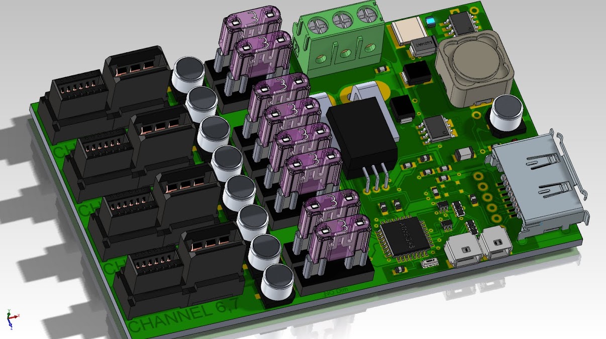
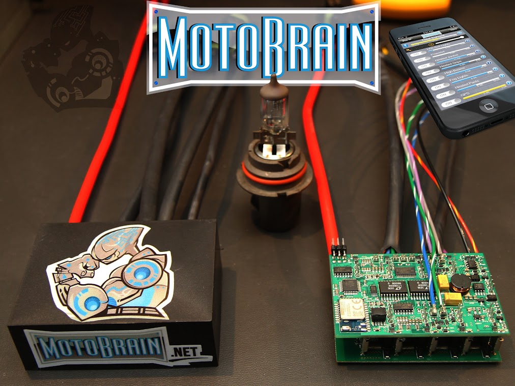
It was going to be controlled from a dedicated unit wired to the gizmo above. The more I thought that through, the more that was foolish since we all have computers in our pockets already, our smart phones. So I did a full reboot and decided to do a Bluetooth 4 gizmo, that was completely weatherproof. That meant I needed to get rid of the fuses and the interchangeable cards. The most practical card was the high side switching card so I decided to go with those. I designed in 8 channels because it was enough for most setups I could imagine and still was a comfortable size to fit on any vehicle. Motobrain was born.

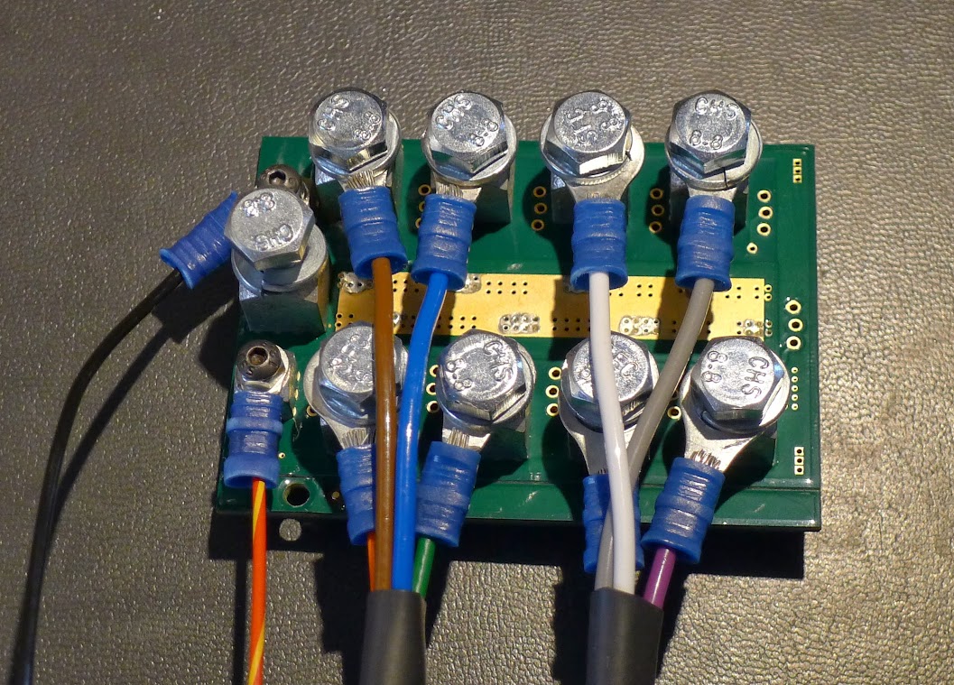
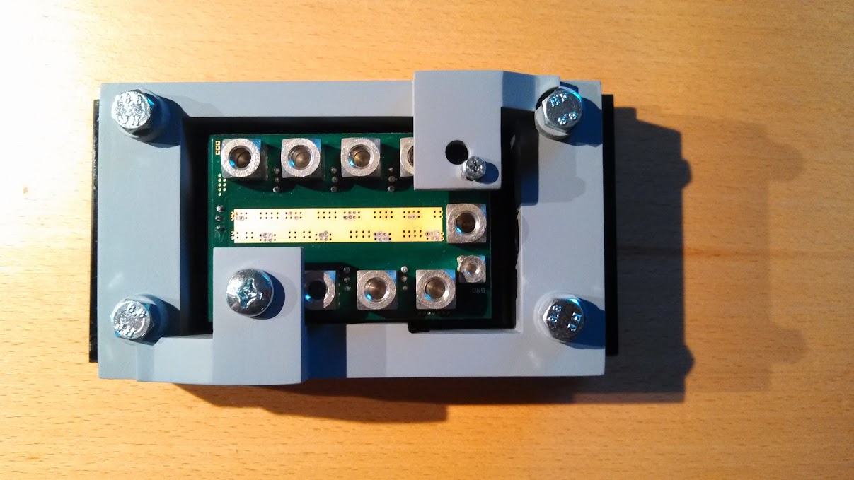

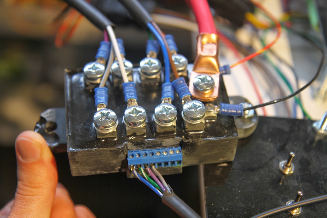
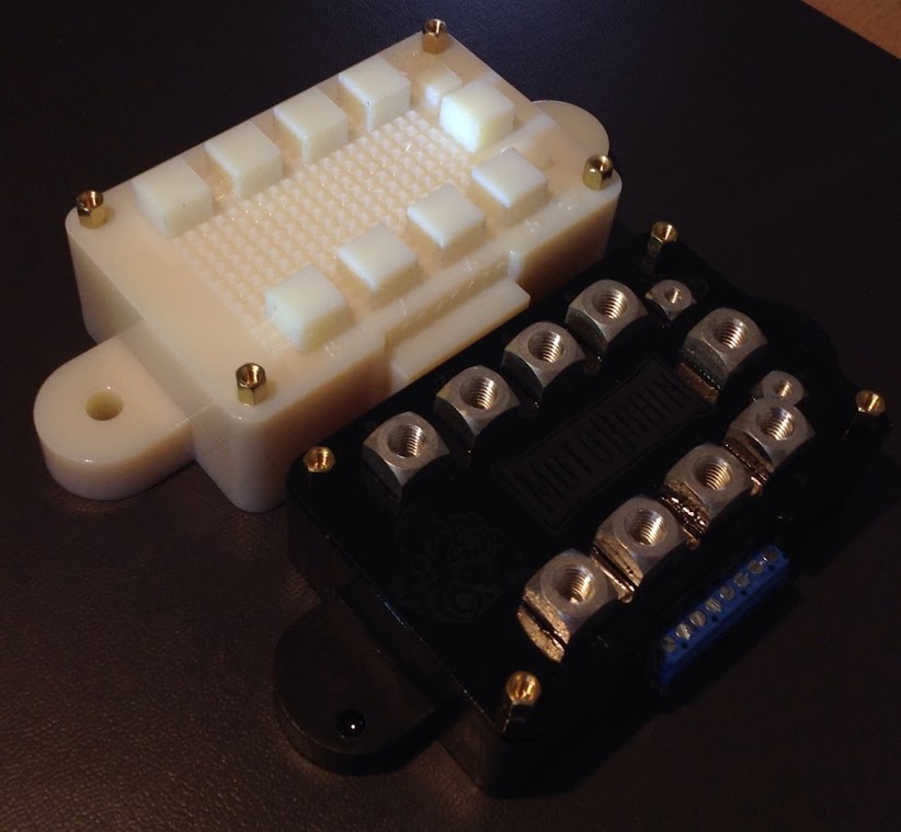

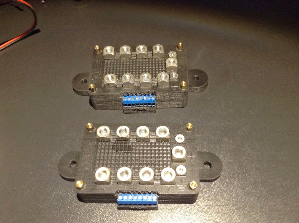
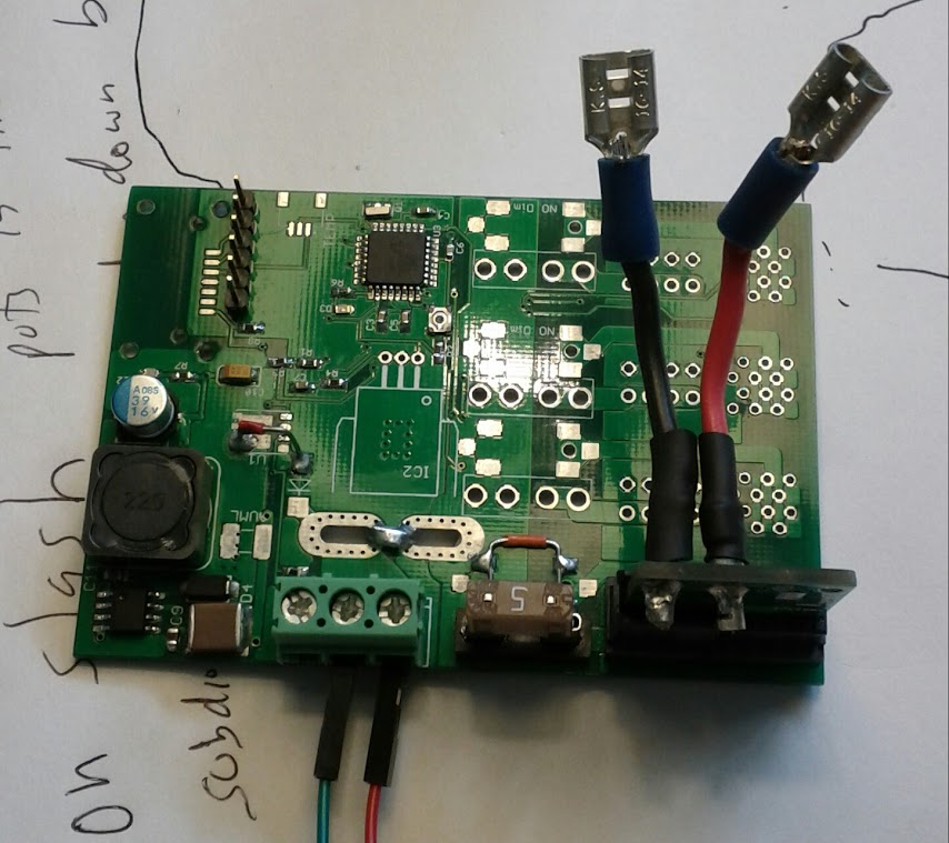
It has gone through several variations mainly surrounding the signal inputs and how the current and signal actually go in and out of the Motobrain. In the photo above, you can see that system was designed with wires terminated inside the potted electronics. That is an easy way to do it but requires that I supply the wire and that it is right for all the customers needs. That seems like a big "if" to me, so redesigned the output board with screw down terminals and I have finally found the product I want to sell.
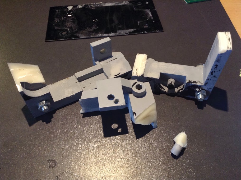
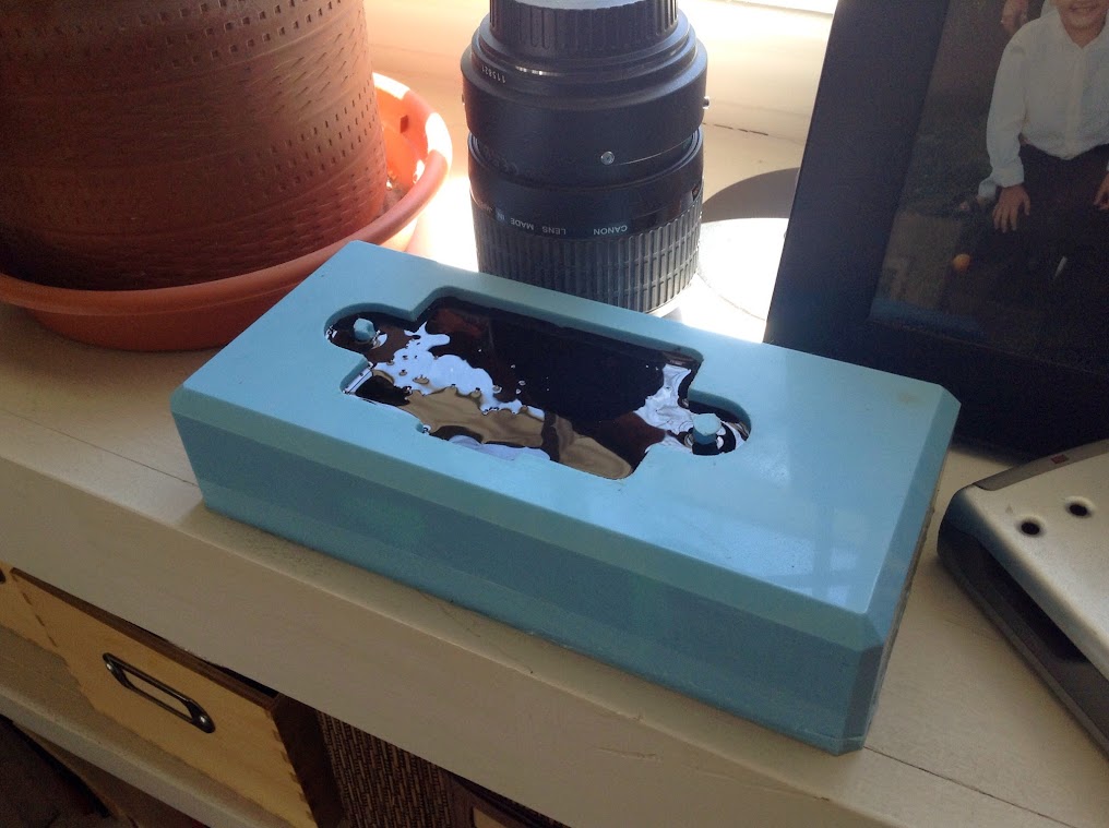
Then I needed to figure out how to cast these things. This is not a skill I've ever learned so it took some time to figure it out. At first, I thought I would 3D print the mold in hard plastic, place the electronics in that and then pour in the resin. It seemed like a fine idea. It wasn't. I burned a couple grand on that before I gave up.
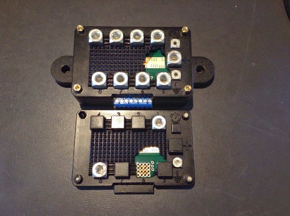
I ultimately got pretty good at this technique...
...but this is just not how to do this job though. People kept telling me to make a silicone mold and it will be easy. I fought the idea because I didn't want to learn yet another skill when I was this far down the road. It was necessary though, so I purchased Solidworks and drew up a perfect replica of Motobrain and had it 3D printed.
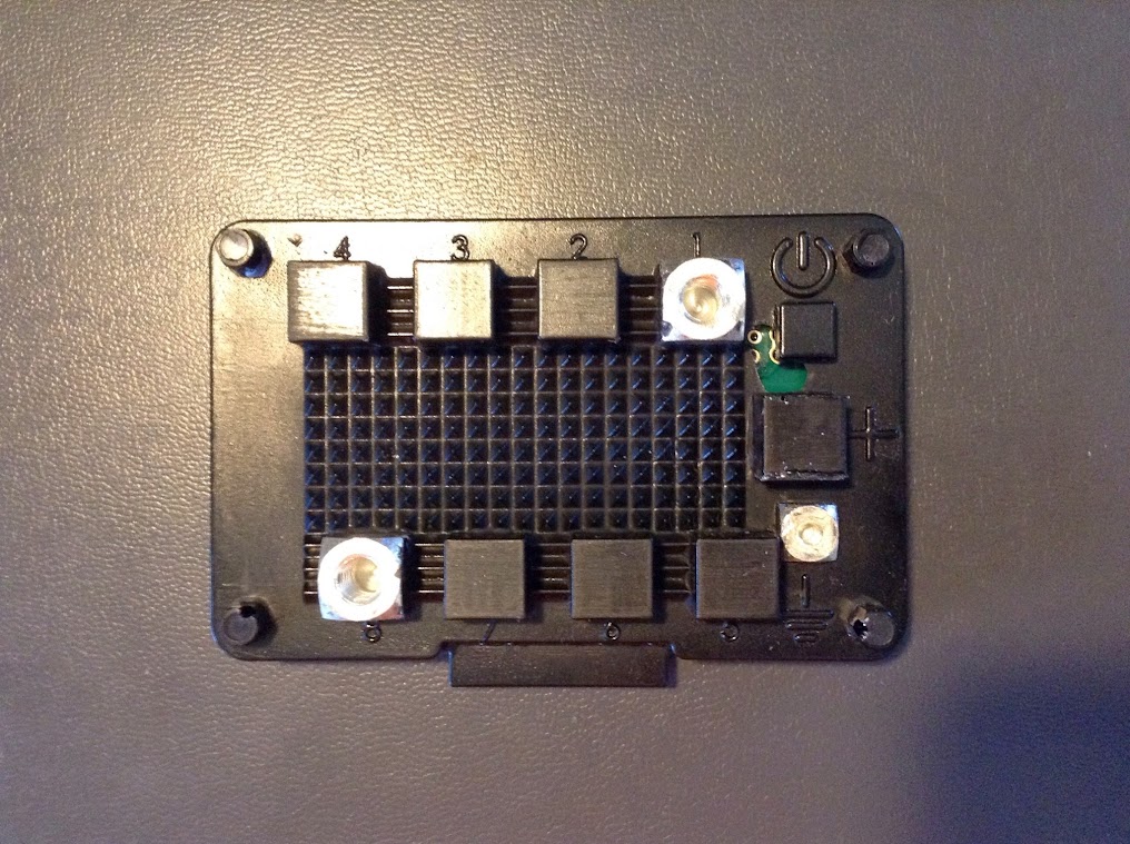
Then I ordered some fancy silicone and cast some fake Motobrains to learn how.
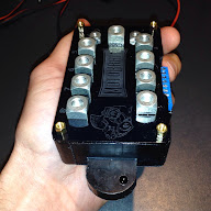
When I was finally confident that I figured it out I made some REAL ones.
Here is where we are today. Read the entire story at our blog.
Comments
Post a Comment