
Thermal imaging macro photography on a budget (sort of)

I purchased one of the new FLIR E4 thermal imaging cameras (TIC) a couple weeks back because I am working on a new project called Motobrain. It is an automotive power distribution unit with a nominal current capacity of 100A. For those not in the know, 100A is a TON of current! Because this project is designed to move so much current and will be small I need to understand its thermal characteristics very well. To that end I've been operating the device and taking measurements. What I found is that I just could not get the kind of detail I wanted. The reason is that the resolution of the microbolometer in the FLIR E4 is not very high and the lens does not allow you to get very close to the device under test (DUT). The means that you cannot just zoom in after you take a photo either. So, what is a person to do if they want to take a macro photograph with a consumer grade TIC? Go to Amazon.com of course! I purchased a Gallium Arsenide (GaAs) lens meant for a CO² laser for about $40 and waited patiently for it to arrive (via ox cart it would seem, it took weeks) from China. Then I mounted it up in a highly technical lens mount (a paper CD case cut with scissors and stapled together with the lens inside). This provides me a focus distance of about 2 inches which is great for close up work on a PCB. Different lens sizes will provide different focusing distances. I chose a 50.8mm lens.
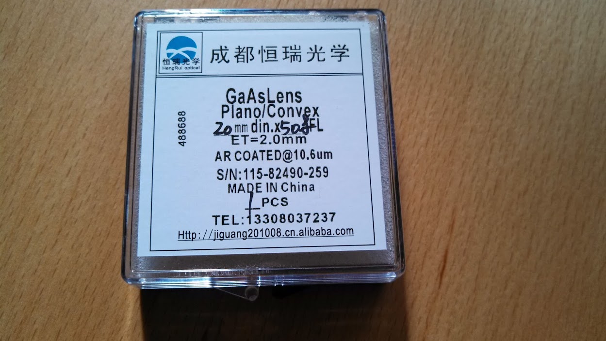
The lens.
The lens installed on the TIC
The photo on the left is with the new macro lens attached. The photo on the right shows the previous closest in focus image I could make. Both photos are looking at the same part of the PCB. My lens mount is causing some vignetting which I can fix if I want to bother to make a nicer lens mount on the laser cutter. Honestly I am quite satisfied with the current image quality. If it ain't broke, don't fix it.
The photo on the left shows an SO-8 PowerPak MOSFET glowing nice and warm. You can even see its drain and gate pins. The photo on the right is the same image from the same distance without the lens installed which shows you what it looks like out of focus. This is a significant improvement at a trivial expense compared to the cost of the instrument.
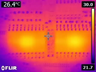
This final image shows the same portion of the PCB as above only with the current flow having just been removed. You can see clearly the temperature gradient as we get further from the MOSFET. Neato!

Special thanks to Mike for the inspiration to do this hack.

Comments

Popular posts from this blog

A Capacitive-Touch Janko Keyboard: What I Did at the 2017 Georgia Tech Moog Hackathon

Last weekend (February 10-12, 2017) I made a Janko-layout capacitive-touch keyboard for the Moog Werkstatt at the Georgia Tech Moog Hackathon. The day after (Monday the 13th), I made this short video of the keyboard being played: "Capacitive Touch Janko Keyboard for Moog Werkstatt" (Text from the video doobly doo) This is a Janko-layout touch keyboard I made at the 2017 Moog Hackathon at Georgia Tech, February 10-12. I'm playing a few classic bass and melody lines from popular and classic tunes. I only have one octave (13 notes) connected so far. The capacitive touch sensors use MPR121 capacitive-touch chips, on breakout boards from Adafruit (Moog Hackathon sponsor Sparkfun makes a similar board for the same chip). The example code from Adafruit was modified to read four boards (using the Adafruit library and making four sensor objects and initializing each to one of the four I2C addresses is remarkably easy for anyone with moderate familiarity with C++), and ...

Atlanta Cosplay Meetup: Group Build Update #3

It's been a while since we posted a progress report for the Atlanta Cosplay Meetup's ongoing project, and with Dragon Con right around the corner, we're nearing the finish line. Let's take a look and see what's been going on the last few months! Check out our previous progress reports here: Progress update #1 Progress update #2 Read on to see where we're at now...

What to Do With a Stack of Picture Frames?

When You Have Too Much Free Stuff! Our newest member Raul got his hands on a stack of about 40 picture frames that were being junked. On a general note Freeside tends to discourage large piles of objects randomly appearing as it tends to collect in corners. Raul got permission from our projects team with a time limit of a few weeks. In this case unnecessary, as the membership more or less attacked the pile of boxes and rapidly rendered them into things. Unfortunately starting off all the frames looked something like this: Not terribly useful. We don't even have any idea who these guys are. After a few passes through the planer, however, we get something like this: A perfectly good picture frame useful for stuff. First idea was to push a couple of these through a the laser cutter. Concept good, aim.... Aim was a little off. Also we had just rebuilt the laser computer and electronics so there were a couple of kinks to work out in CamBam's post processor: &nbsp ...