I've been busy working on this project since I last wrote about it. I have a new PCB designed and built up and another that has since been designed but not yet built. Designing electronics is a process. The first design I had built had an analog mux on it that I was using to push all the current sense signaling to a few ADCs on the board. Later designs needed those pins on the MCU for other purposes so I added an 8 channel ADC to the design and removed the mux all together. I then found that the ADC was too fast to measure the current in a useful way because the PWM I use to adjust the current would give the ADC values that were either 0% or 100% instead of a working average. I knew this going in, but assumed I'd be able to get a reliable average in a reasonable amount of time. For whatever reason though, it took about 300 samples per channel to get an reliable average value. Multiply that by 8 channels and then assume a single byte to store the value and you can see that it consumes at least 2400 bytes (I only have about 500 to work with). It also took about a 12ms to get a value (there was a lot of overhead in the serial communication layer I had not accounted for). Multiple that by 2400 and it would take almost 30 seconds to get reliable current values from all the channels. That was a total epic fail. So, I went back to the drafting table and drew up a circuit that did all the averaging in the analog domain which operates WAY FASTER than any digital circuit can. What I drew up is a three stage low-pass filter for each channel. Image below.
As you can see, the circuit is not exactly trivial (especially if you consider I needed 8 of these added to an already crowded board; 56 more components). The PWM input signal is turned into a low impedance DC voltage source (with the help of an op amp) that is proportional to the duty cycle of the PWM signal and whose DC offset is proportional to the current draw. The second part of that is done with another op-amp and a very large but low impedance resistor and then I do a differential measurement to get the voltage drop across the resistor. I multiply that drop so that the upward bound is just below the top DC rail of the ADC so I get the most bits of resolution. Look up high side current measurement for more details on this. I used LTSpice to help select the values for the RC filter network. The values have a lot to do with the frequency of the PWM input and the speed at which you want it to settle. You can see from the above graphic that I settled on a filter that gives me a decently flat, DC like, signal that settles within 50ms of a current change. This is plenty fast for the purposes of a circuit breaker and should provide excellent user feedback as well. When they turn up a circuit they should see the current like move very fast. This is in fact the case and the video below will show that.
I had another exciting and problematic feature that has been a challenge to create. Market feedback suggested that some constant current capability would be appreciated. At first I thought I may be able to shoehorn this in with a software fix. It turned out to be just too slow to work. When you require constant current you really don't want to overshoot too far or you can fry your load before the circuit has a chance to moderate the current. On the latest iteration of the I added some pretty clever hardware constant current stuff by taking advantage of some features on the MOSFET driver that were for another purpose but could support a constant current function with a little external help. I thought about it for a while and drew up a circuit and had boards built but I never bothered to do ALL the math required to fully understand the circuit I designed. It turned out when it was finished that I didn't understand all the variables that controlled the timing of the circuit. I ended up with a perfectly adequate constant current source, but it oscillated at 20Hz instead of the 200Hz I expected. At first I thought I just dropped a decimal when I was doing the math because 20Hz and 200Hz look suspiciously similar. I redid the math and I had not screwed that up so I had to look more closely to see what was happening. I put it on the scope and then it became quite clear. Remember that 50ms number I mentioned about the settling speed of the 3 stage RC filter I created? Well, if you do the math, you will find that 20Hz is a synonym for 50ms. That was the problem. My filter was too slow to support the constant current feature I wanted to offer. I needed another 10x increase in performance. I knew this was going to be a big challenge and I also knew that my LMV324 op-amps (that were part of the circuit) were not going to be up to the task of moving so fast. I completely redesigned the constant current circuit with high performance op amps and much faster filter. I then went ahead and used LTSpice to model the circuit to confirm the design. This is a somewhat time consuming process, but these 4 layer boards and accompanying stainless steel stencils I am buying cost $200 and take about two weeks to get so its worth the effort to prove out the design before wasting all that time and money.
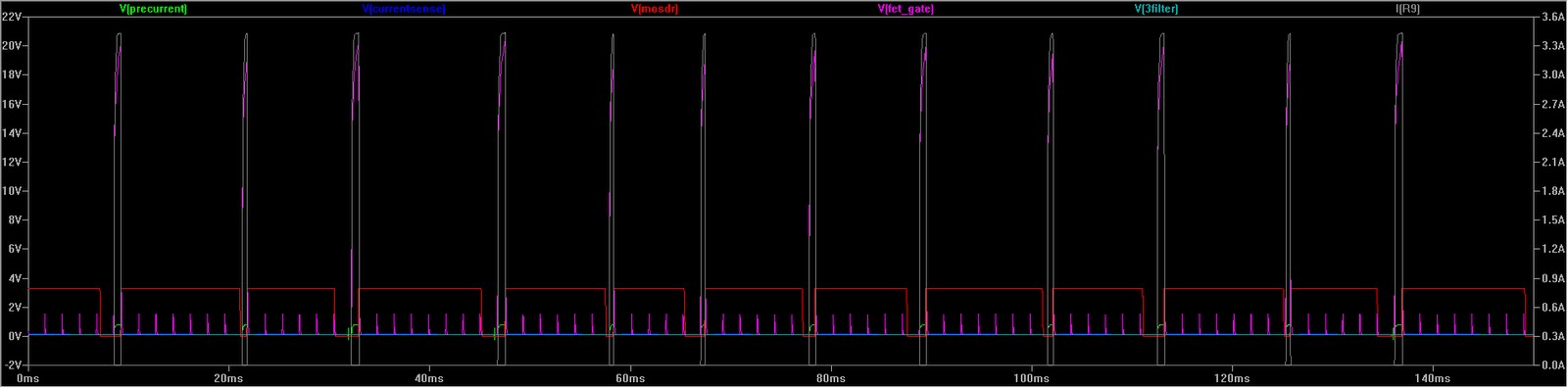
LTSpice is an incredibly useful tool for these sorts of electrical engineering problems. You can see that I am able to get reasonably fast PWM signal that is at a constant current over a roughly 100Hz time frame. The 100Hz speed is a compromise between the slow speed of the former version and fast speed that I desire. My secret sauce here is that I am using only 2 stages of the filter for this instead of 3 and I am adjusting the the first stages a bit. This is the compromise. I could other wise pretty easily get any speed I wanted but I'd have to have even more passive components on the board and its already packed with parts.
I suppose I"ll leave with a couple videos showing the circuit in action.
 |
| Blue: PWM Green: 1st Stage Red: 2nd Stage Celeste: 3rd Stage |
I had another exciting and problematic feature that has been a challenge to create. Market feedback suggested that some constant current capability would be appreciated. At first I thought I may be able to shoehorn this in with a software fix. It turned out to be just too slow to work. When you require constant current you really don't want to overshoot too far or you can fry your load before the circuit has a chance to moderate the current. On the latest iteration of the I added some pretty clever hardware constant current stuff by taking advantage of some features on the MOSFET driver that were for another purpose but could support a constant current function with a little external help. I thought about it for a while and drew up a circuit and had boards built but I never bothered to do ALL the math required to fully understand the circuit I designed. It turned out when it was finished that I didn't understand all the variables that controlled the timing of the circuit. I ended up with a perfectly adequate constant current source, but it oscillated at 20Hz instead of the 200Hz I expected. At first I thought I just dropped a decimal when I was doing the math because 20Hz and 200Hz look suspiciously similar. I redid the math and I had not screwed that up so I had to look more closely to see what was happening. I put it on the scope and then it became quite clear. Remember that 50ms number I mentioned about the settling speed of the 3 stage RC filter I created? Well, if you do the math, you will find that 20Hz is a synonym for 50ms. That was the problem. My filter was too slow to support the constant current feature I wanted to offer. I needed another 10x increase in performance. I knew this was going to be a big challenge and I also knew that my LMV324 op-amps (that were part of the circuit) were not going to be up to the task of moving so fast. I completely redesigned the constant current circuit with high performance op amps and much faster filter. I then went ahead and used LTSpice to model the circuit to confirm the design. This is a somewhat time consuming process, but these 4 layer boards and accompanying stainless steel stencils I am buying cost $200 and take about two weeks to get so its worth the effort to prove out the design before wasting all that time and money.

LTSpice is an incredibly useful tool for these sorts of electrical engineering problems. You can see that I am able to get reasonably fast PWM signal that is at a constant current over a roughly 100Hz time frame. The 100Hz speed is a compromise between the slow speed of the former version and fast speed that I desire. My secret sauce here is that I am using only 2 stages of the filter for this instead of 3 and I am adjusting the the first stages a bit. This is the compromise. I could other wise pretty easily get any speed I wanted but I'd have to have even more passive components on the board and its already packed with parts.
I suppose I"ll leave with a couple videos showing the circuit in action.
Comments
Post a Comment